
Lineup
Specification
Here is our all kinds of UA3P. We will introduce feature and specification.
1. Standard equipment
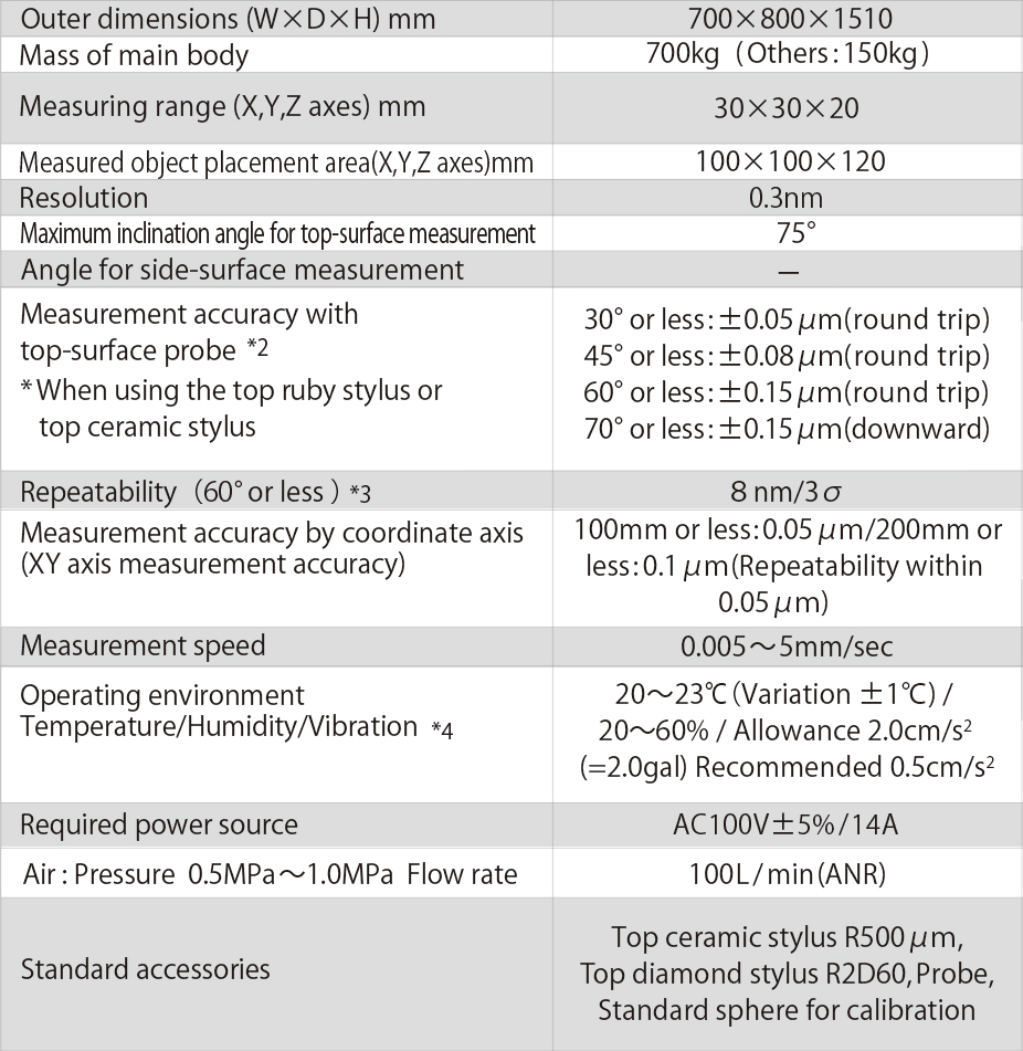
UA3P-300

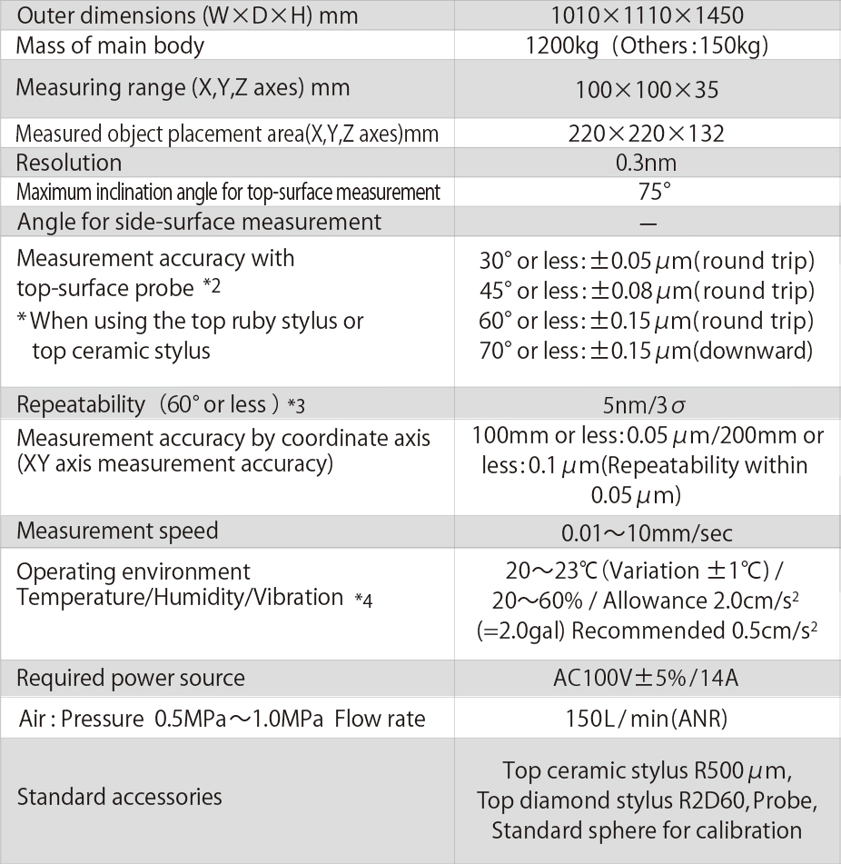
UA3P-400

2. Large-scale equipment
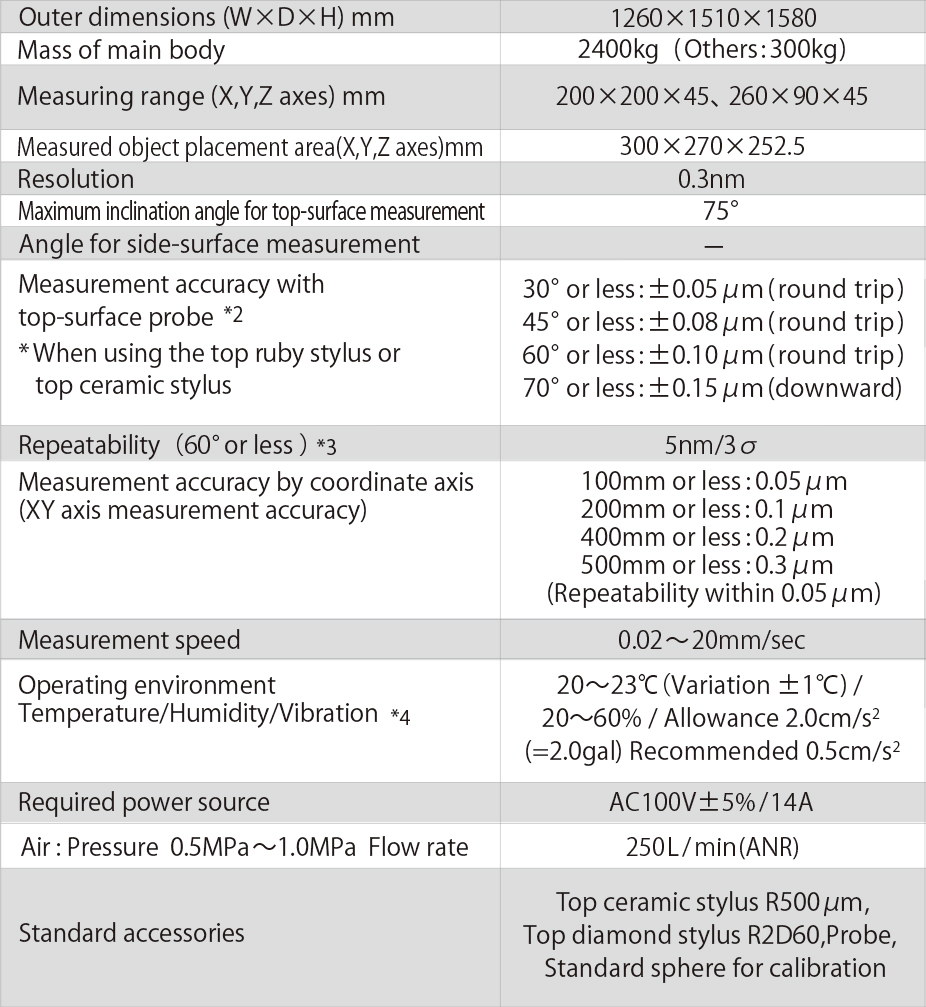
UA3P-500H


UA3P-550H
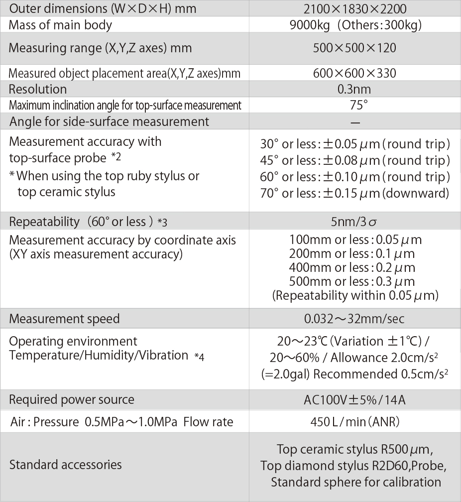
UA3P-650H


UA3P-700H

3. Top-surface and Side-surface profilometer ( Twin probe )
3. Top-surface and Side-surface profilometer ( Twin probe )
UA3P-400T*1


4. High-accuracy equipment
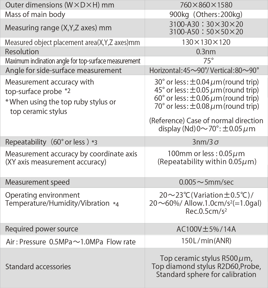
UA3P-3100

UA3P-4000


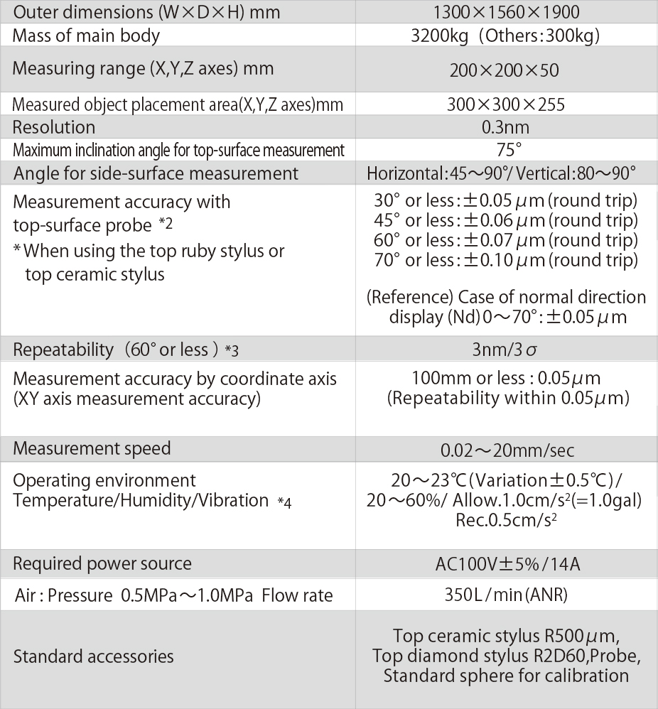
UA3P-5000H

*1: • This product is categorized as a product (or technology) that qualifies as a regulated cargo as specified by the Foreign Exchange and Foreign Trade Act.
• To export or transfer abroad applicable products (or technology) ,you must gain permission for export in advance from the Japanese government.
*2:Includes shape error of the standard sphere
*3:According to our measurement regulations
*4:Wind from air conditioners should not directly blow onto the equipment
*5:EU Data Act
- Transparency Notice
- Data specification
Ultrahigh Accurate 3-D Profilometer(UA3P Series)
UA3P Specifications List

Option
UA3P options for measuring a wide range of shapes
Hardware
Mechanics options | Details | |
|---|---|---|
1 | Auto Tilt Stage (2 Axis, 3 Axis) | Mechanism that automatically corrects the tilt of a measuring object based on its measured data. |
2 | Wafer Chuck & Stage | Adding an air chucking stage and recognition camera for wafer lens measurement. |
3 | Decenter and Tilt measuring Jig (various types) | Jig used for decenter and tilt measurement (used in combination with option software [9]) |
Stylus for top-surface measurement

Top Diamond Stylus R 2 D 60
(PED-16100112)

Top Ceramic Stylus R 500 μm
(PED-1610M079)

Top Diamond Stylus R 2 D 60 (L=12mm)
(PED-16100116)

Top Diamond Stylus R 2 D 45 (EM)
(PED-1610M106)

Top Diamond Stylus R 2 D 30
(PED-1610M052)

Top Diamond Stylus R 5 D 45
(PED-1610M077)
Stylus for side-surface measurement

Side Ruby Stylus φ2 mm
(PED-1630M020)

Side Ruby Stylus φ 1 mm
(PED-1630M021)

Side Ruby Stylus φ 300 μm
(PED-1630M022)

Side Ceramic Stylus φ 1 mm (L=30mm)
(PED-1630M035)

Side Carbide Stylus φ 80 μm
(PED-1630M024)

Side Carbide Stylus φ 30 μm
(PED-1630M025)
Decenter and Tilt measurement jig
Decenter/Tilt measurement between lens faces
The lens is fixed on a jig provided with three reference balls for combination. Any decentering between the lens faces is evaluated by measuring both faces of the lens.


Observation camera
Applicable model: All models
A measuring point is magnified for display to enable easy positioning.

Wafer level lens (WLL)
Applicable model: UA3P-500H/650H/700H

* Precautions
*1 Note that the ruby stylus is at risk of breaking due to its large coefficient of friction while measuring aluminum lenses or surface-coated lenses.
*2 The stylus for side-surface measurement (Φ30 µm - Φ300 µm) may require an observation camera for measurement.
◆ In addition to the contents described, we prepare a variety of stylus, such as different size and material. Please contact our sales for detail.
Software
Software Option | Details | |
|---|---|---|
1 | Circular scanning measurement function | Adds circumferential scanning NC paths for measured objects with a hole in the center. |
2 | Top Flat centering function | Function that enables centering of a measuring object whose center is nearly flat. |
3 | User-defined formula function | Function to evaluated by user created formula. |
4 | Aspherical coefficients fitting function | Function to fit aspherical coefficients based on measured data. |
5 | Diamond stylus correction function | Function to correct stylus tip shape based on standard sphere measured data. |
6 | Point cloud data design formula creation function | Function to generate a spline curved formula based on points cloud converted from CAD data (provided by the customer) |
7 | One million data points sampling, captureing 2000 points per second function | Function to expand the number of measurement points and to increase the speed of capturing data points. |
8 | Waveguide software (offline) | Function to evaluate the dimensions of the shape of an object based on the measured data. |
9 | Decenter and tilt evaluation software (offline) | Function to evaluate decenter and tilt of lens front and back using the jig installed 3 sphere. |
10 | Automatic Measurement Software | Function to create measurtement procedure program and to execute procedures automatically. |
11 | Wafer lens measurement software | Function to measure and evaluate wafer lenses in combination with mechanical option [2] |
Circumferential scanning measurement software
The measured object is circumferentially scanned and measured.
- Hollow objects are also measureable.
- Up to 1200 concentric circles.

User-defined software (free-form curved surfaces, etc.)
Other formulae are supported in addition to the lens design formula that is registered as a standard feature.
The use of the C language for creating the design formula and the calculation part of a partial differential equation allows all of ISO10110-12 to be covered.

Software for creating point group data design formula
A rectangular curved surface is created using the spline function with respect to given 3D point group data.


Fitting software (rotation symmetry)
A previously unknown design formula of a measured object can be obtained from the measurement data.

Auto-measurement
Applicable model: All models except for UA3P-400T

Fully automated, including probe movement and focus ON/OFF
Supporting various errors
* The jig is prepared by the user
Contact
Contact us for any question about the UA3P.