
About UA3P
This page introduces the UA3P policy, its main areas of application, and its evolution.
Policy
Based on our philosophy of "Manufacturing is not feasible without measurement," we offer nano-level measuring equipment with a wide variety of models.
The UA3P series can measure aspherical lenses and free-form mirrors and their molds, which are essential for digital consumer electronics such as mobile phones, DSCs, DVDs, and Blu-ray recorders, as well as in home security, optical communications, and vehicle HUDs, to an accuracy of 0.01 µm.
Easy operation supports rapid feedback to machining.
We will seek ever-greater accuracy in measurement and will continue to drive our product evolution.
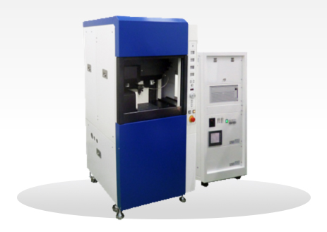
Small model: Best suited for measuring camera lenses for smartphones
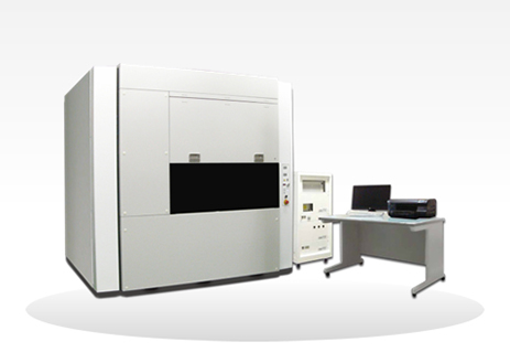
Large model: Best suited for HUDs and astronomical products
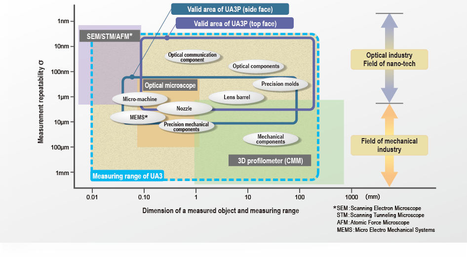
Measurement accuracy and applicable field of each profilometer
Measurement accuracy and applicable field of each profilometer
Evolution of UA3P
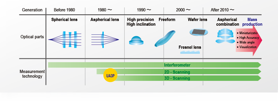
Evolution of Optical Components and Measurement Technologies
Based on our unique technical developments, the measurement of aspherical lenses with high accuracy has been put to practical use. Since then, the UA3P has evolved by fulfilling customer requirements.
Progress of required optical parts and development of measurement technology
Standard equipment in the lens industry
In the smartphone lens industry, the UA3P is recognized as the standard equipment for highly accurate measurement. UA3P technology, created in Japan, supports all of Panasonic's business areas: Consumer electronics, housing, automotive products, and B2B. The UA3P, now used worldwide, is contributing to support a wide range of developing technologies.
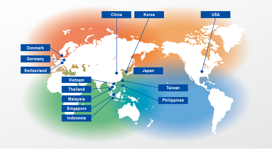
*Delivery country
Feature
Here is our UA3P's Technology.
"Laser method / High precision probe / Software"
Coordinate measurement technology
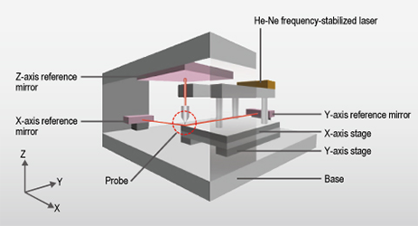
Coordinate measurement technology
The profilometer's coordinate system is configured with three reference flat surfaces (mirrors) independent of the stages. The length of each X, Y, and Z axis is measured to a resolving power of 0.3 nm with the laser interference method using a He-Ne frequency-stabilized laser as a light source. This suppresses the influence of squareness and straightness of the stages to achieve high-precision measurement.
- Measurement error due to coordinate axis:0.05 µm max. (up to 100 mm), 0.3 µm max. (up to 500 mm)
Measuring probe
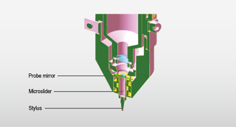
Top-surface measuring probe/AFP
High-precision scanning and measurement of a measured object is feasible due to the use of ultra-low measuring forces.
The stylus is held by the micro-air slider, and the focus laser detects the movement of the stylus. The position of the AFP is tracked in line with the shape of the measured object to keep the measuring force constant.
- Measuring force: 0.15-0.30 mN (15-30 mgf) * UA3P-3100/4000 requires 0.05~0.30 mN, UA3P-5000H requires 0.10~0.30 mN.
- Stylus:A diamond stylus with a tip angle of 30 and a radius of 2 µm can be used.
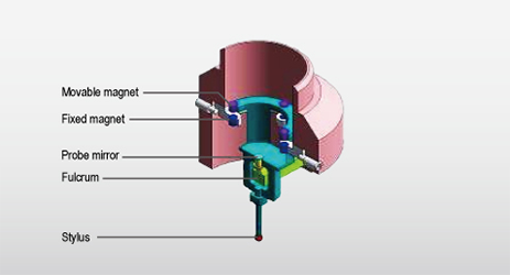
Side-surface measuring probe/S-AFP
The inclination of a probe mirror detected at high precision is fed back to the XY stages to enable scanning measurement with low-contact force (0.3 mN).
This enables measurement without deforming resin products, such as a lens barrel.
- Measuring force: 0.3 mN (30 mgf)
- Measurement accuracy: ±0.15 µm (when measuring 90° inclination)
- Maximum measuring angle:Horizontal measurement:45° - 90° (angle relative to horizontal surface), Vertical measurement:80° - 90° (angle relative to horizontal surface)
Software
Achieving high-speed and high-precision measurement with easy operation Supporting any design information. An installation error in the measured object is three-dimensionally corrected to enable accurate profile measurement.
Design information input
Supporting any design information
- Optical design formula
- 3D point group data
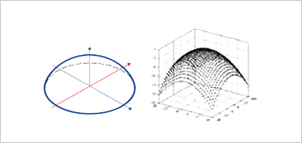
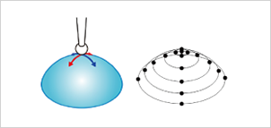
Centering and measurement
The center of the measured object is found to scan and measure on its axis and plane.
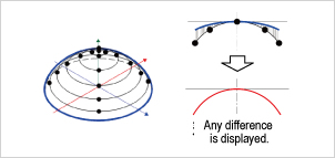
Alignment
Numerically identifying a difference between the measurement data and design formula.
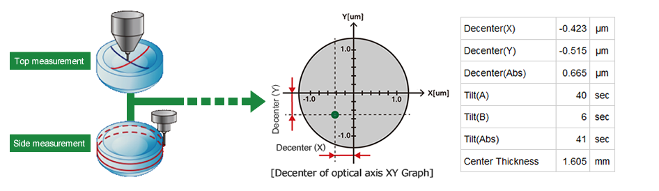
Top side surface evaluation technology
Top side surface evaluation technology
By synthesizing the top-surface data and side-surface data of a measured object, decentering and inclination of the optical axis of a lens or a mold can be evaluated with reference to the side surface.
Contact
Contact us for any question about the UA3P.